The following article is from the Fall 2018 Shot Peener magazine.
 by Bryan Chevrie, Product Engineer with Electronics, Inc.
As I write this, it is getting close to that time of year again. That’s right, you guessed it, the EI Shot Peening US Workshop. For some of you that means buying plane tickets and booking a hotel. For others it means buying costumes and putting up Halloween decorations. However, this year, I’m super excited, because my wife and I will be running our first Spartan race. I know what some of you are saying right now, “But Bryan, aren’t you an engineer? And I thought engineers didn’t have any measurable upper body strength to run an obstacle race and didn’t like the outdoors?” And you would be correct if I were a stereotypical engineer, but I’m not. I love physical actives such as lifting weights, HIIT (High Intensity Interval Training), swimming, and running. I also prefer to be outside, where there are fewer engineers—some of those people are crazy.
The rest of you readers are probably asking yourself, “Bryan, what does running a Spartan race have to do with MagnaValves? And, are you ever going to get to your point?” And, yes, there is a point to be made here. Before my wife and I signed up for a Spartan race, we first researched what a Spartan race was and what type of obstacles were involved. This allowed us to compare our current physical ability to what would be required to complete the race. Once we made this comparison, we were able to design a training regimen to concentrate on our weaknesses.
It would be foolish to just signup for a Spartan race without first knowing if you are physically and mentally up for such a demanding challenge. For the physically fit, this may work out fine in the end. For the less physically fit, this could turn into complete failure.
Likewise, it would be foolish to purchase a MagnaValve, mount it below a media hopper, connect it to whatever 24 Vdc power supply is inside the cabinet of the machine and hope it works. This situation may work okay on an OEM’s shop floor but may turn out to be a disaster at the customer’s facility. For some this sounds obvious; however, we see this happen all too often.
The MagnaValve appears to be such a simple device. Put a hopper full of shot above the MagnaValve and you get the requested flow rate below the MagnaValve. What can go wrong? Well, for starters, a lot. The MagnaValve’s performance and life span can be affected by pressure differentials between the pressure pot and the blast hose, improper start-up and shut-down sequencing of the blast air and shot flow, and coupled noise from high-voltage devices such as motors, just to name a few life-threatening situations for the MagnaValve.
I’m hoping to uncover the deep secrets of MagnaValve installation and use over several articles, but today I’m going to concentrate on MagnaValve basics, specifically the 5xx-24 Vdc MagnaValve. The 5xx-24 Vdc MagnaValve is the family of valves that control the flow rate of ferrous media. I know this is the boring stuff, but some basic knowledge will go a long way when Murphy and his law (anything that can go wrong, will go wrong) stops by to visit or takes up permanent residency. I know some of you can relate. You pray every night that he moves into your buddy’s house or better yet, your competitor’s. However, until he moves out, we must be prepared to deal with his disruptions.
So here we go—the 24 Vdc MagnaValve is made up five parts. The five parts are the Supply and IO Line Filter, System Electronics, Valve Driver, Media Flow Valve, and Sensor. I’ll briefly go over each part.
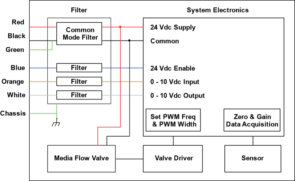
Figure 1. The Five Parts of a MagnaValve
Supply and IO Line Filter
The filter blocks any high voltage transients and high frequency noise that may be present on the wiring connected to the MagnaValve. You may have noticed that the GREEN wire and the BLACK wire are connected internally. Also notice that the GREEN wire is NOT connected to ground or the chassis. In earlier versions of the 24 Vdc MagnaValve, the BLACK wire was signal common for the System Electronics while the GREEN wire was the signal return for the Valve Driver. However after some customers invented new and unique ways of destroying the MagnaValve, we added additional filtering. Thank you for that by the way. To keep the 24 Vdc MagnaValve directly replaceable with older versions, we tied the GREEN and BLACK wires together internally.
The Chassis should be connected to earth ground through the machine. This is typically done through the plumbing of the machine; however, if the plumbing is not a reliable grounding connection, a ground clamp can be connected to the pipe of the MagnaValve.
The brass pipe of the MagnaValve is the best Chassis ground connection. The enclosure and the filter ground are connected to the brass pipe internally. So please DO NOT drill a hole in the side of the enclosure to attach a ground wire.
System Electronics
The System Electronics contains all the logic of the system. The System Electronics reads the 0 – 10 Vdc Input Signal, sets the 0 – 10 Vdc Output Signal, monitors the 24 Vdc Enable Signal, reads the Sensor Signal, and sends the control signal to the Valve Driver
The System Electronics reads the 0 – 10 Vdc Input Signal and converts it to a 0 – 100% PWM (pulse width modulation) signal that is sent to the Valve Driver. The frequency of the PWM is controlled by the Pulse Hz potentiometer on the front of the MagnaValve. The duty cycle of the PWM signal is based on the 0 – 10 Vdc Analog Input, where 0 Vdc input equals 0% duty cycle and 10 Vdc input equals 100% duty cycle.
The System Electronics reads the Sensor Signal and converts it to a 0 – 10 Vdc Output Signal that represents 0 – Maximum Flow Rate (the Maximum Flow Rate is programmed through a terminal program).
The System Electronics also monitors the 24 Vdc Enable input and commands the Media Flow Valve to flow media when an Enable Signal is applied.
For those that want to use the MagnaValve without a FC-24, one thing to note is that the PWM signal is derived from the 0 – 10 Vdc input and not the Sensor signal. The Sensor and the Valve Driver are two separate stand-along systems. This set-up with the 0 – 10 Vdc Input and 0 – 10 Vdc Output allows the MagnaValve to be connected to the FC-24 Controller or direct connection to a PLC with a programmed PID controller.
Valve Driver
The Valve Driver is an amplifier that will take the PWM signal from the System Electronics and control the Media Flow Valve. The Valve Driver contains all the high current components and generates most of the heat in the MagnaValve. Some of you may have noticed that the body of the MagnaValve gets warm to the touch after media flow. This is normal.
The Valve Driver not only takes the 0 – 100% PWM signal to control the flow rate through the Media Flow Valve, but also adjusts its amplitude. This ensures the MagnaValve will flow the maximum amount of media that it is physically capable of flowing.
Media Flow Valve
The Media Flow Valve contains the brass pipe the media flows through, the permanent magnet that stops the media flow, and the power coils that allow media to flow. Using a permanent magnet to stop the media flow makes the MagnaValve a normally closed media valve. This means that if there is a loss of power or the machine is shut down, the hopper will not empty into the blast hose. A very important note: While the MagnaValve is a normally closed media valve, it can NOT hold back air pressure. If the MagnaValve is used in a direct pressure application, it must have a pinch valve mounted directly below the MagnaValve. (Mounting the pinch valve below the MagnaValve is the preferable installation method.)
To get a better sense of the flow rate in response to the 0 – 10 Vdc Input Signal, see Figure 2. Figure 2 shows an example of the flow rate through the MagnaValve as the Analog Input voltage changes. This is not a linear relationship. This graph is called the Open Loop Profile of the MagnaValve. This profile will be different for each media type and size. The media type that works in the 5xx-24V MagnaValve is ferrous media, such as cast steel and steel cut wire. Cast stainless media will not work in the 5xx-24 Vdc MagnaValve. The reason cast stainless media will not work is because it is not magnetic or it is weakly magnetic.
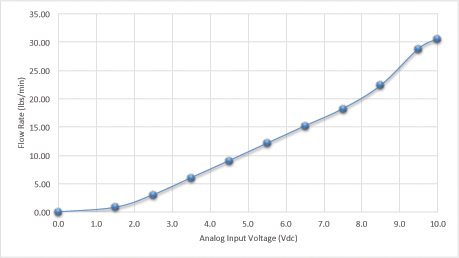
Figure 2. Example of open-loop performance of
a 24 Vdc MagnaValve.
Sensor
The Sensor does just what it says. It senses and measures the flow rate of the media flowing through the MagnaValve. The sensor is an inductive type sensor and therefore it works very well with ferrous material. Many customers, however, do not understand the basic operation of the sensor, so I’ll give an overview here.
When the MagnaValve is calibrated before shipment to the customer, a catch and weigh test is conducted. This is where the Open Loop Profile is created, see Figure 2. Each one of the points on the graph in Figure 2 represents a catch and weigh test. During the catch and weigh test a look-up table is created. The following is the procedure:
1. Set the analog input voltage to the value of interest.
2. Apply the Enable Signal for a set time (one minute makes the calculation easy). The Sensor Signal is recorded during this time.
3. After the set time, weigh the amount of media dispersed by the MagnaValve.
4. Calculate and enter the flow rate into the MagnaValve.
5. Repeat for all points.
6. Set the Maximum Flow Rate in the MagnaValve.
You maybe asking, “What does all this mean and how does the MagnaValve use this information?” And these are very good questions.
The MagnaValve uses this information to determine and set the 0 – 10 Vdc Output Signal. The Output Signal is 0 Vdc with 0 lb/min flow rate and 10 Vdc with Max Flow Rate. To see the sensor’s output response to flow rate, see Figure 3. The Max Flow Rate value sets the scaling of the analog output. Notice that the maximum flow shown in the Open Loop Profile of the MagnaValve (see Figure 2) is approximately 30 lb/min, but shown in Figure 2, the analog output is 10 Vdc when the MagnaValve is flowing 20 lb/min. This is because the 0 – 10 Vdc Output Signal is scaled for 0 – 20 lb/min, where 20 lb/min is the Max Flow Rate.
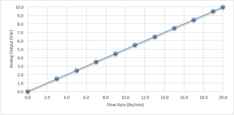
Figure 3. Example of the Analog Output voltage
with respect to Flow Rate.
I hope this article helps provide a better understanding of the 5xx-24 Vdc MagnaValve. I know that for many the MagnaValve is just a black box both literally and figuratively. I’m going to keep bringing you articles that will provide in- depth information like this to ensure a successful integration of the MagnaValve into your equipment.
So please say tuned.