The following article is from the 2020 Spring Shot Peener magazine. It was written by Jack Champaigne, President of Electronics Inc.
Many blast cleaning and shot peening processes benefit from non-ferrous media (ceramic bead and glass bead) because the media eliminates contamination such as rust. It is often assumed that the media is free of all iron contamination, either new or in use. SAE specifications J1173, J1830, AMS2431/7 and AMS 2431/6 state that the magnetic particle shall not exceed 0.1% of the original sample, by weight. Descriptions of an inspection method are included in each of these documents as follows.
This inspection method should be performed on all new media prior to introduction to the machine and on a frequent basis. An easily avoidable source of contamination is using ferrous and non-ferrous media in the same machine. It is impossible to get all the ferrous media out of the machine so contamination is all but guaranteed. Another source of contamination is erosion of the blasting machine and even dislodged machine parts.
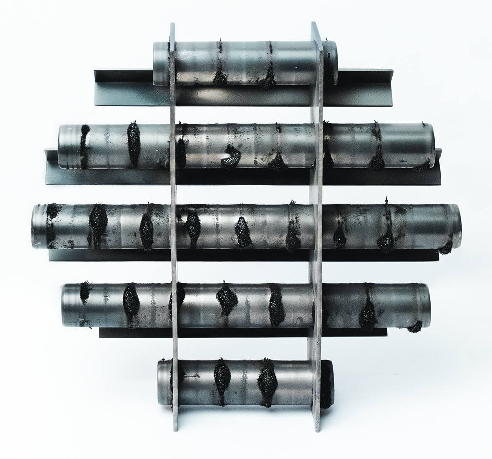
Magnetic traps should be installed on machines to extract the iron contamination and these need frequent inspections and cleaning. Below are examples of bar-type magnetic traps.
Magnetic Separators
Author’s note: The following information is from Eriez—“the world authority in separation technology.”
Magnetically susceptible metal contamination (iron) is commonly removed using magnetic separators. There is magnetic separation equipment that traps metal using ceramic or neodymium iron boron (neodymium). Ceramic magnets produce low strength but deep reach magnetics fields, while neodymium magnets create the strongest permanent magnetic products presently commercially available.
High-strength magnetic fields, as produced by neodymium, are needed to capture fine iron metal contamination. These are the main magnet configurations suitable for handling powders:
a. Tubular magnetic cartridges, often in a multi-rod grate configuration
b. Flat-faced magnetic plates
c. Cone-shaped magnets
d. Magnetic drums with a curved magnetic arc
Although occasionally a magnetic cartridge may be used on its own, it is more commonly part of a larger multi-cartridge grate system. The magnetic grate is designed to fit inside a hopper, or can be supplied complete with a housing (as a drawer filter magnet).
In operation, powder falls freely onto the surface of the magnetic cartridge where fine iron strikes the surface and is held by the strong magnetic field. To ensure that the powder makes contact with the cartridge surface, deflectors are often deployed above the gaps between the cartridges.
Powder build-up on the surface of a magnetic cartridge will reduce the separation efficiency. Also, in severe cases, a slight build up on the surface of the cartridge may quickly cause a blockage of the whole housing.
Such blockages can be prevented by ensuring that there is optimum space between the magnetic cartridges. Also, in some cases, the mounting of an external vibrating motor on the side of the hopper or housing will provide enough disturbance to prevent any material coagulation. The frequency of the vibration needs careful consideration as it could affect the flow ability of the powder.
Additionally, when vibrators are used, the magnetic cartridges need to be manufactured to withstand prolonged periods of vibration.
Flat-faced magnetic plates are ideal when it is possible for the material to flow over the surface. For fine iron removal, the magnetic plates would use high strength neodymium magnets. This magnetic field is further enhanced when a tapered step is added to the face of the magnet. Captured iron migrates behind the step and away from the material flow, reducing the risk of re-entering the cleansed product.
As well as being fitted into chutes, magnetic plates are incorporated into housings. The plate housing magnets resist bridging and choking to remove tramp iron and ferrous fines from flow-resistant bulk materials. The stainless steel housings mount easily to enclosed spouting or directly on processing equipment.
There are optional square, rectangular, and round adapters for easy connection to existing chute work. A baffle at the top of the housing helps break up clumps and directs product flow over the unit’s two powerful plate magnets. Plate magnets are used in in-line magnets with two designs:
- Gravity in-line magnets: The plate magnets are positioned in round, sloping spouting where material is under gravity flow. For effective tramp metal capture, the sprouting should be angled no more than 60˚ from horizontal.
- Pneumatic in-line magnets: These designs are for use in dilute phase pneumatic conveying systems (up to 15 psi). They can be installed easily with optional factory-supplied compression couplings and work best in horizontal runs with the plate magnet down to take advantage of material stratification.
Another design of in-line magnet is the center-flow although the magnetic field is generated in a cone configuration instead of a plate. The magnetic cone is positioned in the center of the housing, allowing the powder to flow in the space left between the housing. Center-flow in-line magnetic separators are commonly used in dilute-phase pneumatic conveying lines up to 15 psi.
To achieve optimum contact with the product flow, a conical magnet is suspended in the center-line of the housing. This tapered, exposed-pole cartridge has a stainless steel “nose cone” to direct the flow of materials around the magnet. The tapered poles of the cone magnet allow ferrous fines to collect out of the direct air stream. Additionally, the trailing end of the magnet is an active magnetic pole and holds any tramp metal that is swept down the cone.
Both types of in-line magnets are designed with clamps and doors to enable easy access for cleaning.
In specific applications, a high-strength neodymium drum magnet will enable the best level of separation. The drum magnet is gravity-fed, usually via a vibratory feeder. The drum magnet has a stationary high-strength magnetic arc positioned inside a rotating outer shell. When material flows onto the drum magnet, the magnetic field projected by the stationary magnetic assembly inside the shell captures fine iron and holds it securely to the drum’s stainless steel surface. With contaminants removed, the good product falls freely to a discharge point. As the drum rotates, the captured fine iron travels along the drum surface and out of the magnetic field, where it is discharged.
There are various magnetic field configurations possible, but the most suitable for removing iron from powder is one that produces a radial magnetic field. This ensures that once captured, the fine iron does not leave the drum surface until it moves out of the magnetic field.
Processing powder on a drum magnet presents more difficulties that other designs of magnetic separators. First, it is recommended that the vibratory feeder has an air bed to produce a consistent feed of powder. Standard vibratory feeders may deliver powder in clumps, significantly affecting the separation performance.
Second, the shell of the drum magnet should be rotated at high speeds.
This will result in some of the powder pluming, and this can be minimized by keeping the distance between the end of the vibratory feeder tray and the rotating surface of the drum magnet to a minimum.
The high rotation speed of the drum magnet significantly reduces the amount of product lost to the magnetics. This is because there is less material on the surface of the drum at any one time, reducing the chance of entrapment. Drum magnets operating at high rotational speeds are successful in removing fine iron from abrasives, refractories, and other applications where the material has a high specific gravity.
As the demand for finer and purer powders increases, so does the need to remove even the finest iron. Understanding the properties and behavior of the powder is vitally important when considering the optimum method of fine iron separation. Often the ultimate solution is a series of magnetic separators and metal detectors located at strategic points within the process.
Magnetic Separators at Electronics Inc.
Electronics Inc. (EI) uses a magnetic separator on an airblast machine in their testing laboratory. The photo below shows how much ferrous contamination was captured by EI’s airblast machine’s dust collector with a grate magnet. The debris is erosion of the cabinet walls and tooling as it gets abraded by the media. After seeing such positive results from using magnetic protection, the EI engineering staff has invested in additional magnetic separators.