The following article is from the Winter 2019 Shot Peener magazine.
 by Bryan Chevrie, Product Engineer with Electronics, Inc.
You might remember from my last article that my wife and I set out on a journey to become Spartans. Well on the 20th of October in the year 2018 we stormed the Toyota Stadium and walked away VICTORIOUS! It was so much fun and yet challenging. I was able to overcome all obstacles presented before me, but one. The Spear Throw. If I was living in Sparta in 435 B.C. and I threw a spear the way I did that day, I would have been dragged behind a horse until dead.
Next year, I plan on going for the Trifecta and I will nail the spear throw. For those that don’t know what a trifecta is, it is three races (a 5+ km, a 13+ km, and a 20+ km) all in the same calendar year.
In the continuing pursuit of successful MagnaValve® installations, I am going to discuss power supply connections and requirements. I know for some, this sounds like simple stuff. It is only three little connections. How in the world could someone screw that up? But we see MagnaValves and controllers in less than ideal installations all the time.
On the surface, it seems so easy: Connect the positive supply, the common, and ground, and you’re done. Well you must start by selecting a proper supply. Most people get that correct; however, everything that is connected to that supply draws current from that supply and these currents MUST be managed. This is where everything falls apart.
Many people understand that current leaves the supply and travels down a wire to some device, such as a MagnaValve. However, some people fail to consider that this current must return to the power supply from which it came. The layout, path, and all the connections within this loop are very important.
To add complexity to this problem, there is the return current path back to the supply and there is ground. These are NOT the same thing. But they often get treated like they are the same thing. Bruce Archambeault stated it perfectly in his book titled “PCB Design for Real-World EMI Control.” He wrote, “If inductance is one of the most commonly misunderstood concepts, ‘ground’ is the MOST misunderstood.”
Earth Ground
Let’s talk a little about Earth Ground to start with. Earth Ground is just that—the big round thing that you stand on, or that thing you hit when you slip on ice. The earth has an electrical potential; we call this potential 0V and often we use that as a reference. Everything else that sits on or floats above it has an electrical potential that is greater than, less than, or equal to the electrical potential of the earth.
Humans can become a path for current to travel between two objects that has an electrical potential greater than or less than 0V. If this current is great enough, it will make for a very bad day for that human. Sometimes this is done intentionally—it’s called the electric chair.
To prevent humans from touching things they shouldn’t touch and to protect the stupid ones, we put metal boxes around everything that has an electrical potential greater than or less than the earth. Then we take a wire and bond those metal boxes to the earth. That way we can ensure that both the metal boxes and the earth are at the same electrical potential. As a result, when a human is standing on the earth and touches one of those metal boxes, they don’t “feel the power.” That is called Earth Ground, not to be confused with Chassis Ground, which is different.
Chassis Ground
Chassis Ground, in the simplest form, is using the body or chassis of the equipment as the ground connection point for all electrical devices that are bolted to the equipment.
It’s a giant terminal block, if you will. The equipment is then connected to Earth Ground. An example of this might be all the electrical conduit and plumbing on a peening machine. To have a wire connect to each pipe fitting or conduit fitting would not be feasible. Therefore, all the piping, conduit, and fittings are manufactured from metal and attached to the machine using metal fasteners. Now if the machine is properly attached to Earth Ground, any human that touches the conduit, plumbing, or the machine itself will not have a shocking experience.
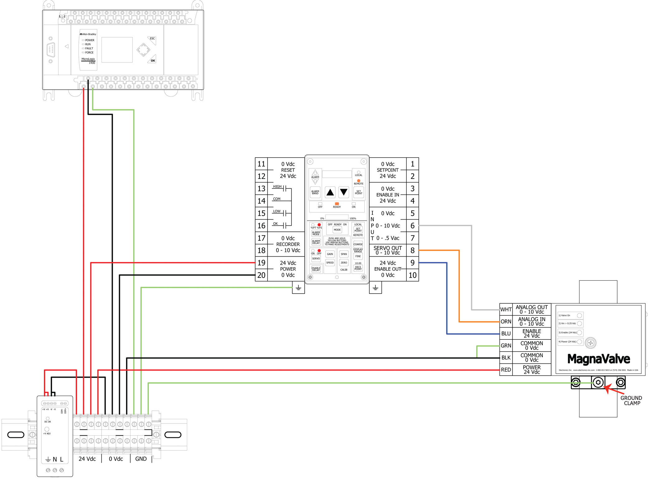
Another example of Chassis Ground is the transient and over-voltage protection in the MagnaValve. Any time there is voltage surge on the supply lines or an ESD (Electrostatic Discharge) to the enclosure of the MagnaValve, all the excess energy is redirected to the pipe of the MagnaValve. (Variable Frequency Drives for motors use this same technique; more on that in a later article.) The pipe is typically grounded through the plumbing of the machine. If the plumbing is not a sufficient grounding connection, then a ground clamp (see Figure 1) could be purchased to connect the MagnaValve directly to the ground bar in the panel.

Figure 1: Simple MagnaValve wiring diagram.
Shielding
Shielding, which has a very specific function, is unrelated to human safety. Shielding could be required for a device or wiring to a device. This shielding maybe necessary for the safety of the device or to prevent electrical magnetic interference to the device itself or other devices close by.
One example of shielding is in switching power supplies. If you have ever looked at a switching power supply and thought to yourself, “Boy they sure put a lot of effort into the enclosure. They had to punch all those holes in that cool pattern and bend all those flanges so neatly.” That wasn’t done to look nice—that metal enclosure must be connected to Chassis Ground or Earth Ground and it picks up and redirects all the magnetic radiation that the electronics are creating to the Chassis or Earth Ground. This prevents that magnetic radiation from interfering with electronics close by that may be sensitive to magnetic radiation.
Another example of shielding is a shielded cable. Many controls engineers and panel electricians never give much thought to what happens when current travels through a wire. As current travels through a wire (specifically an AC power signal, a pulse, or a PWM), a magnetic field is generated surrounding that wire. As current travels in one direction, the magnetic field expands and if it stops or changes direction, the field collapses. And the opposite will happen when a wire is located in an expanding or collapsing magnetic field—a current is generated in the wire.
If there are two wires in a conduit and there is a changing current traveling through one of the wires, the magnetic field surrounding that wire will be expanding and collapsing. The other wire located in the same conduit will be experiencing the expanding and collapsing magnetic field and therefore will have a forced current travel through it. This poor routing could induce noise in a sensor signal or cause a PID loop to become unstable along with various other problems. Proper panel layout and proper wire routing will prevent these types of problems from occurring; however, when there is no forethought in planning the panel layout and how the wires should be routed, shielded cable often become the band-aid to fix a problem that should have never existed.
Supply Selection
One of the questions that is often asked is, “How big of a supply is needed to operate a MagnaValve?” We recommend 2A per MagnaValve / controller combo. Some MagnaValves use less current than others, but 2A per valve and controller is a good rule-of-thumb and will work for all MagnaValves.
Figure 1 shows the start of a typical installation. Here we have a 5xx-24 MagnaValve, a FC-24 controller, a PLC, and a 24 Vdc power supply. The 24 Vdc supply will supply power to the controller, MagnaValve and PLC.
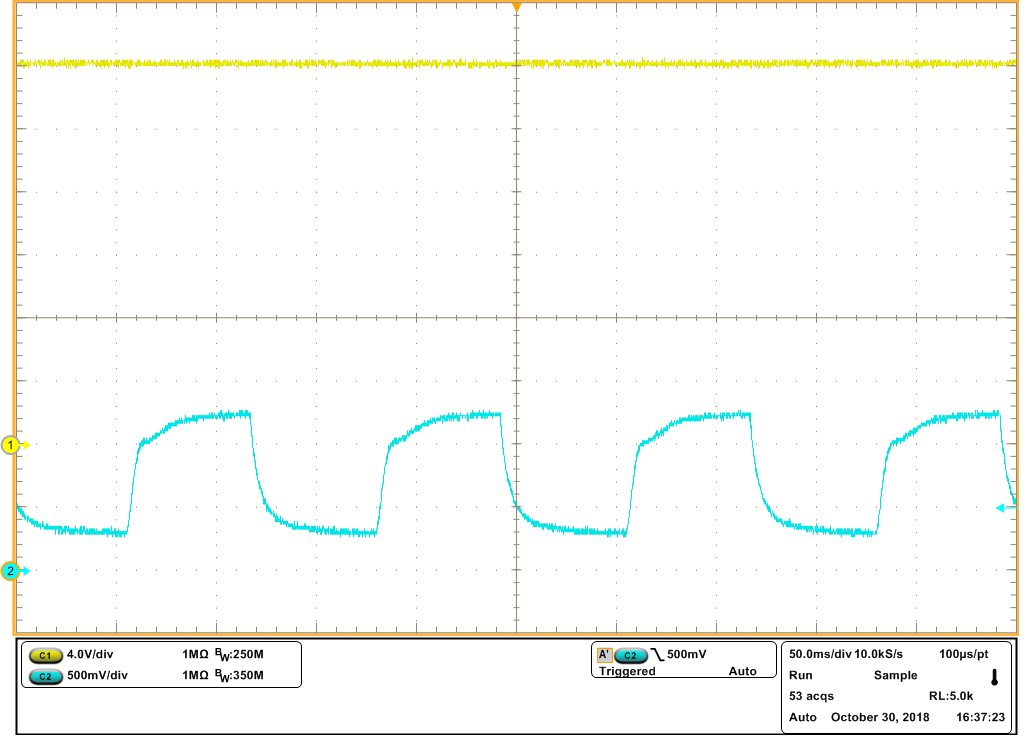
In this example, the 5xx-24 MagnaValve is the device that will pull the most current from the power supply. And more importantly, the MagnaValve uses a PWM signal to control the flow rate of shot. Figure 2 shows the current and voltage waveforms for a MagnaValve set to 50% duty cycle and powered by a 24 Vdc @ 2A supply. Notice there is approximately 1.25A for current draw and no clipping or voltage droop.

Figure 2: Normal MagnaValve operation at 50% duty cycle with 2A supply.
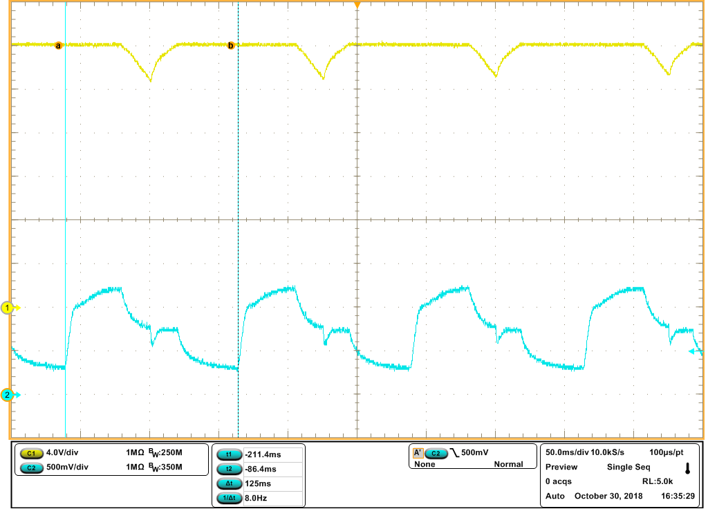
You might be wondering, “What would happen if the supply was too small?” Very good question. Figure 3 shows the same setup but using a 24 Vdc supply with a 0.75A limit. Notice the current and voltage waveforms. There is approximately 3.5 Vdc of droop on the voltage supply and an excessive amount of distortion in the current. Not only does this affect the performance of the MagnaValve, but it also creates high-frequency harmonics that could disrupt nearby sensitive electronics.

Figure 3: MagnaValve operation at 50% duty cycle with 0.75A supply.
A few additional considerations: In Figure 3 notice that this is a changing current (pulsing) and it has the potential to cause interference in sensitive electronics. The power supply wires for this device MUST be routed with care. It is highly recommended that the power supply wires to the MagnaValve be connected to the power supply terminal block in a STAR connection (see Figure 1). This means a direct connection to the terminal block without daisy chaining to other devices. If more than one MagnaValve is installed on a machine, each MagnaValve must have its own connection directly from the terminal block.
I hope these articles are taking some of the mystery out of that Black Box known as the MagnaValve. I will keep revealing the hidden secrets. For next time, there is plenty more on grounding, panel layout, and routing.
