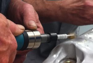
 SAE AMS2590A, Rotary Flap Peening of Metal Parts, was released in November, 2016 and it has several important changes to the original version introduced five years ago. Dave Barkley, the EI Shot Peening Training Director and a SAE Committee B Board Member, was the sponsor of Revision A.
Mr. Barkley’s article in the spring issue of The Shot Peener magazine outlines the changes to the specification and we will cover the most significant ones in this article.
Section 3.1.4 (test strip holder)
This section is what prompted Mr. Barkley to sponsor the five-year review for AMS2590. “I had noticed in 2010 that a dimension error from the 1972 MIL specification had been carried over to AMS2590. The initial goal was to correct only this dimension error, but I realized I had the opportunity to make improvements inspired by the rotary flap peening training I’ve conducted over the years. I felt the magnetic test strip holder was too restrictive in design while not being specific enough on its proper use. It’s important to note that care was taken to include these design improvements without obsoleting the existing magnetic strip holder,” he wrote in The Shot Peener article. Revision A allows some latitude in the type of backstop used on the Almen strip holder based of successful techniques Mr. Barkley has witnessed in facilities utilizing rotary flap peening.
Section 3.4.1.1 (verification of tool speed)
Section 3.4.1.1 is new. It was established because a tool’s speed is far easier to verify than intensity on regular intervals. The direct relationship between intensity and RPM will insure the proper intensity is maintained by verifying the tool’s desired RPM and that it is constant. Tachometers and stroboscopes are now listed as tools used to verify RPM before saturation curve generation, intensity verification, and application of the process to any single work area. If a single work area is very large, the elapsed time between RPM verification cannot exceed 60 minutes. Intervaled RPM verification is not required if a closed-loop rotary tool is used.
Section 8 (notes)
The only change to “notes” was to section 8.3. It was renamed “Equipment Recommendations” to draw more attention to its contents. This may be the most beneficial part of this article for some. This section previously discussed only how increasing a pneumatic tool’s torque capabilities may cure variations in tool RPM, however this isn’t a sure fix.
“My travels around the world have found too many shops that are not properly regulating the air pressure to the tool. A good high-torque tool will only be as good as the air supplied to it. Using only a single regulator, or flow controller, to set a tool’s target RPM will not maintain a consistent RPM. A second regulator upstream from the tool is needed to stop cycling system pressure from getting to the tool. If system pressure cycles between 100 and 120 psi, the upstream regulator can be set to 90 psi and fed to the tool with a dedicated hose. I recommend everyone with pneumatic rotary tools do this in effort to keep consistent tool RPM—confirmed with a tachometer or stroboscope,” said Mr. Barkley.
“Unfortunately, not all air systems can maintain enough pressure and/or volume and varying RPM may remain an issue. Small pipe diameters, the distance from the compressor, and other factors might make a fix impossible. If this is the case for your pneumatic (or electric) rotary tools, I highly recommend investing in a tool with closed-loop RPM control,” he added.
We encourage you to download the article in its entirety and to obtain your own copy of the new AMS2590A by visiting the SAE website (http://standards.sae.org/ams2590a).


